VRoom! blog - Vector ALU Patterns
19 Jun 2023Introduction
Last time we talked about how we would approach building our RISC-V vector instruction implementation, here we’re going to talk a bit more about how we plan on doing it.
Background
We selected an initial design where the renamer breaks each vector instruction into multiple beats - issuing cloned copies of the instruction into the commitQ. This has the advantage that they can then be executed out of order and be spread among multiple vector ALUs and be executed in parallel wherever possible.
Remember that a RISC-V vector instruction essentially has two parts - an instruction, and a separate length/shape that describes how it’s executed - so you might set up a shape of “‘32-bits’ length = 45” in a register the vector unit will execute 45 32-bit adds - on a 512-bit implementation it would fit 16 32-bit values into a register and as a result 45 32-bit entry vector will fit into (45=16+16+13) 3 512-bit SIMD registers. So we can do a 45 entry 32-bit vector add in 3 clocks - the RISC-V vector architecture makes it easy to write portable code that runs on 512-bit, 256-bit, or even 64-bit register systems without change.
We’re going to use this example (a 45 length 32-bit operand 3 register operation) in all our diagrams below - in reality individual operations can be from 1-8 registers in length, and the way that register length fields are managed makes it easy to create loops that process much longer vectors of arbitrary length.
Implementation
We expect (with a few exceptions like division and sqrt) each vector instruction that reaches a vector ALU will be executed in a fixed number of clocks (likely 1 for integer ALUs, 2 for multipliers, 2/3 for floating point add/multiply) - splitting these up into individual units makes scheduling easier (and more efficient).
The register files here are going to be big - 32 architectural and likely 64 in the commitQ buffers, for routing reasons we’ll not share the commitQ buffers with the integer/FPU ALUs it’s better to keep those registers near the ALUs they feed. Remember our ALU designs are intended to be regular, amenable to hand layout/routing - so we don’t work too hard on the verilog models other that as a synthesisable example for correctness and testing we want the real thing to be fast.
The register width in this design is variable (as a compile time variable - verilog generate FTW) - for the moment any power of two between 64 and 512 (512 is our the cache line size, architectures larger than that will need extra load/store unit work) - we’ll be testing with 512-bits.
Examples
The main point of this blog entry is to crystalize some of the design patterns we’re going to use for what we’re going to call the VRE (‘vector renamer expander’) which is the unit that’s going to expand individual vector instructions into multiple ‘beats’ or simple ALU instructions
1. A simple example
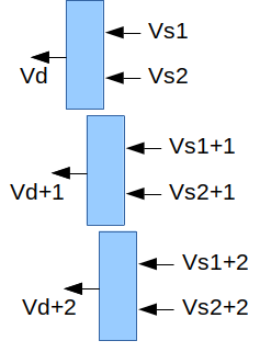
Consider a simple vector add instruction ‘vadd.vv vd, vs2, vs1’ this along with the current vector length register really mean that it is effectively N SIMD register adds - if N is 3 then we’re going to break these up into ‘vadd vd, vs2, vs1; vadd vd+1, vs2+1, vs1+1; vadd vd+2, vs2+2, vs1+2’ - our renamer can throw these into the commitQ as 3 entries, because their source registers are independent of their destination registers they can be executed out of order (only limited by when their source registers become available).
Partly here we’re trying to explain the relationships that renamed vector registers are going to end up having - blue boxes below represent individual commitQ entries, arrows represent register dependencies, (if Vs1 is register V4, Vs1+1 would be V5). Individual commitQ entries will be mapped to real vector ALUs when all their registers become available, if there’s no dependency relationship between blue boxes they can be executed in any order.
2. A more complex example
Most RISC-V vector instructions have an optional bit mask that enables whether or not a particular field is operated on or not - in some cases unmasked fields (in the destination register) retain their original values. Implementing this means reading the previous value of the destination register, and the bit mask registers which is always in register V0.
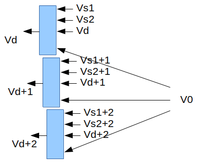
This gives us the general ‘shape’ for each functional unit - a write port and 4 vector read ports (actually an integer or FP read port too) - there’s some scope for simplification of the mask read port - it always reads architectural register V0, but still needs to be renamed like any other register.
3. Widening
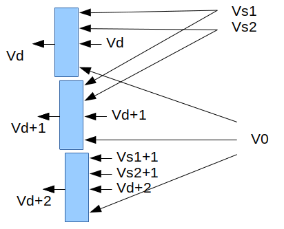
There’s a class of instructions that convert data of one size to data of twice that size, for example “vwadd vd, vs2, vs1, vm” might add together two 16-bit values to make 32-bit ones.
These instructions need to fetch source registers at half the rate - they’re going to look like this:
4. Narrowing
There’s a similar set of operations where data of one size is narrowed to another - for example from 32-bits down to 16-bits. In this case we need to read data from two registers to make each output register, in this case the renamer needs to be able to make dependency graphs that look like this.
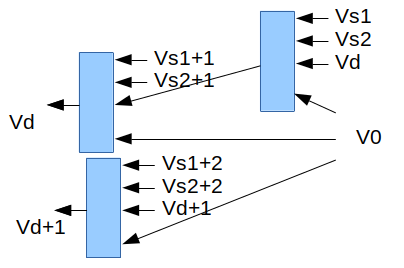
Notice how we now have a dependency where we didn’t have one before - we need to create Vd, but it needs to read two sets of registers and so it needs two clocks (two ALU slots) to get the register file bandwidth to be executed. The upper 2 blocks each write register Vd, but to non-overlapping portions of it (they could be done in either order).
More examples
There are lot of patterns for different instructions, we’re not going to cover them all today, but let’s talk about a couple of the more interesting that we’re still thinking about:
Many-to-one patterns
There’s a class of vector instructions that perform an operation on all the values in a vector to produce a single result, for example: vredsum.vs vd, vs2, vs1 adds up vs[0] and all the values in vs2[*] to make a single scalar sum that is deposited into vd[0].
If we have vector ALUs that can add N 64-bit (or 32-bit) values in a clock - then with 512-bit registers and our 45 entry 32-bit example we can add 16 32-bit registers from a register to make 8 32-bit sums, we can then add 2 registers each with 8 32-bit sums to make 1 register with 8 32-bit sums ….
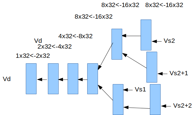
As you can see this sort of pattern tends to have a log2 N sort of depths of structures, only the early portions of the process can be parallelized.
Random access patterns
There a small number of instructions that essentially randomly access values in another vector - in a system that renames registers this is a particular problem and may result in stalling the renamer, consider the vector gather operation that takes a vector of offsets to select entries within another vector, it’s essentially for i Vd[i] = Vs2[Vs1[i]] - the renamer has to rename each Vs1 (remember a vector might be 45 items long but only stored in 3 registers, it’s the registers that are renamed), then get something into the commitQ that reads the renamed Vs1 register, when that’s done the renamer needs to be able to rename the indexed Vs2 register and put that into the commitQ to write the final Vd output - these will probably need to be done entry by entry, there’s not a lot of parallelism available here - gather instructions are likely going to need work to stop them becoming bottlenecks. (There’s still lots of work to be done here)
What’s Next?
More work on integer ALUs, a modified renamer.
Next time: More Vectors!
